If you want to make your own blind controller but don’t want the hassle of the electronics or simply like the idea of a more compact and safe design, I have created a custom Printed Circuit Board (PCB) which can be purchased via eBay.

Assembly of the blind controller using the custom PCB boards is relatively straight forward, insert the listed components into the labelled slots and solder in place. Here I’ve listed a few useful hints to save you a bit of time in the process and make sure everything goes smoothly…
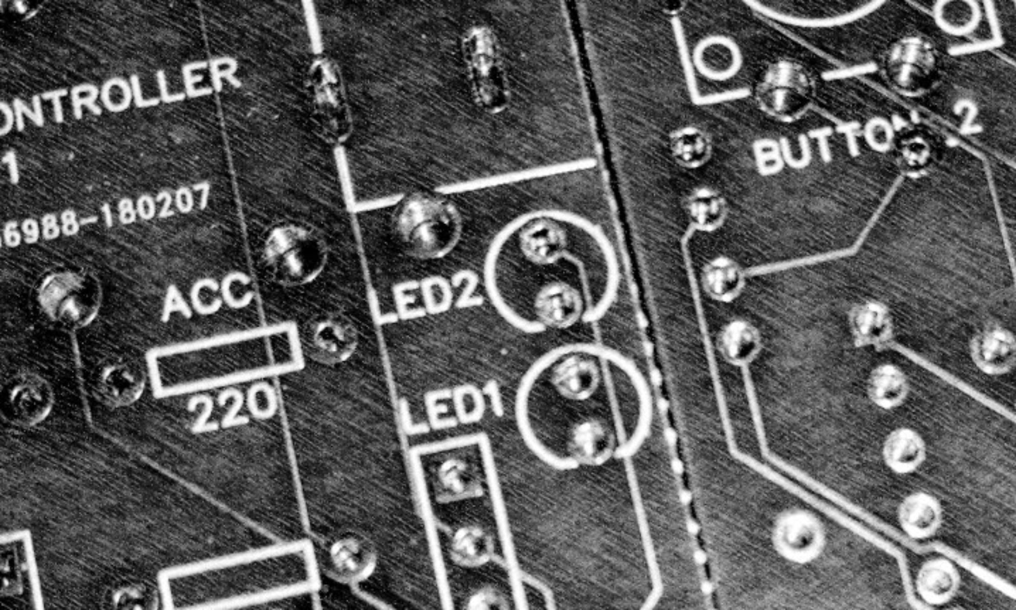
Note: Everything but the two buttons are soldered to the same side of the board, check using the photos below before starting out and I advise checking components before soldering as removing them once they are in place can be difficult!
- Solder the resistors: The resistors simply drop into place and should approximately match the indicated ratings. Cut away any excess wire.

- Solder the DC jacks: It is important to do this before the buttons as otherwise you may find one of the button pins clashes

- Add header sockets for Arduino Nano and L298N Motor Driver: Solder 2x15pin female header sockets for the Arduino nano. Although the L298N motor driver can be dropped straight in to the board, you may want to consider using a header socket here too as these allows for easy replacement should this component ever fail. The positive pin of the L298N should be nearest the bottom edge of the PCB board.
- Solder buttons: One button will slot into place without any modification. To save space the second button sits very close to the accessory jack. Cut off the leg whose mounting whole is blocked (this will not effect the working of the controller in any way)
- Solder LEDs: Yellow at the bottom, green at the top, the short leg (cathode) of both leds should be inserted at the top (nearest the buttons).
- Solder the RF reciever: This should slot into place with the GND pin nearest the bottom edge of the PCB board. You may want to consider using a header socket as used earlier but there may not be space in the current design to accommodate for this.
- Insert Arduino: Slot the Arduino nano in place being sure that pin D12 of the nano is alongside the + pin of the L298N (You need to solder pins to your nano in such a way to achieve this).

- Upload the latest sketch: Attach the nano to the USB and upload the latest sketch using the Arduino IDE.
- Connect motor and test: Connect 2 pins from the motor to the L298N, power the controller from the jack at the bottom of the board using a minimum 5V (Center pin positive). Note: The jack is labelled as 12V but I recommend a maximum voltage of 9V.

- If everything is working as expected, assemble the electronics inside the housing using screws or hot glue and complete the assembly of the blind controller. If something does not work or behaves unexpectedly check connections using a multi meter and replace any suspect components. I have had broken L298Ns and RF controllers in the past.
- Calibrated the controller by pressing and holding the buttons to raise or lower the blind to the required start/end position, then (when the orange light is not lit) press and hold until the full extent of required travel has been achieved. Now whilst the orange light is lit hold down the same button and the controller will flash to confirm that this time has been saved to memory. Repeat for the other direction. This may take some time to get perfect, modification of timings in the sketch itself may be easier. An alternative solution is to install the magnetic end stop sensor using the accessory port, details of which can be found on thingiverse. Good luck!